The HackPWM Platform
Concept
The basic idea is to allow the user to create powerful PWM Systems with a small, but flexible set of Program Blocks which can depend on other signals, so it can provide continuous PWM signal output, signal cascading, phase shifting, signal counting etc.
Pins
Which pins can be used for what.
OUTxPins: OUT1, OUT2, OUT3, OUT4, OUT5, OUT6 can be used aspin,wait_pinandcount_pinwith internal programs. But external signals can not be applied to those pins.GP0xPins: GP02, GP03, GP04 can also be used as well aspinand aswait_pin/count_pinfor external signal sources. Keep in mind, thatGP0xpins have only 3.3V output voltage and should be used to drive signals only. If using as inputs for external signal sources, they must be protected appropriately. The engineer should maintain an input voltage at about 3.3V. For more info see RP2040 Datasheet (opens in a new tab) 5.5.3. Pin Specifications.
Built-in Program Blocks
We are going to explore the built-in program blocks, but custom program blocks can also be created by more advanced users. See source code: https://github.com/webdeb/nanoshim/blob/hackpwm/src/hackpwm/programs.py (opens in a new tab)
PWM - Program
pid= "PWM"
Configugration parameters:
-
labelThe name of the program, "F1", "My PWM 1" .. -
pinThe signal out pin -
wait_pin(optional) The pin which enables the PWM Program to run a full cycle.wait_pincan be one of the OUTx pins, and also the GPIO pins likeGP02,GPO3,GPO4for external signal sources, like feedback loops etc. -
wait_level(optional, default=1) The level of thewait_pinwhich enables the PWM.
UI Settings:
- F: The frequency of the signal. Up-to 25Mhz (with wait_pin: 20.8 Mhz)
- D: The duty cycle. From 16ns. Can be set to % or absolute time by holding the MODE Button.
Examples:
The output depends on the actual settings in the UI, like the frequency and the duty cycle. The following examples are just for demo purposes.
Basic PWM

{
  "title": "Simple PWM System",
  "programs": [
    { "pid": "PWM", "label": "F1", "pin": "OUT1" }
  ]
}
PWM with wait_pin

With an internally controlled pin
{
  "title": "PWM with Ref",
  "programs": [
    { "pid": "PWM", "label": "Ch1", "pin": "OUT1", "wait_pin": "OUT2" },
    { "pid": "PWM", "label": "Package", "pin": "OUT2" }
  ]
}
Or an external pin as input.
{
  "title": "PWM with Ref",
  "programs": [
    { "pid": "PWM", "label": "F1", "pin": "OUT1", "wait_pin": "GP02" }
  ]
}
PUSH PULL - Program
pid= "PUSH_PULL"
The Push Pull program is almost the same as PWM Program and supports the same configuration parameters, but differs from the PWM program only as it runs first the full period for the configured pin and then it runs the same period for pin+1. This is why you should pay attention which pin you configure.
Configuration parameters:
-
labellike Push Pull, H-Bridge or CH12.. -
pinThe first signal out pin. Keep in mind, that the PUSH PULL Program will acquire pin+1 automatically. -
wait_pin(optional) The pin which enables the PWM Program to run a full cycle -
wait_level(optional, default=1) The level of thewait_pinthat enables the PUSH PULL Program.
UI Settings:
Same as PWM, but the max frequency is only about 12.5Mhz because of the double PIN process.
Examples:
The output depends on the actual settings in the UI, like the frequency and the duty cycle.
PUSH PULL

{
  "title": "PushPull",
  "programs": [{ "pid": "PUSH_PULL", "label": "Push Pull", "pin": "OUT1" }]
}
PUSH PULL with wait_pin

The program will end its cycle, before it is going to wait mode again.
{
  "title": "PushPull",
  "programs": [
    { "pid": "PUSH_PULL", "label": "Push Pull", "pin": "OUT1", "wait_pin": "OUT3" },
    { "pid": "PWM", "label": "Mod", "pin": "OUT3" }
  ]
}
PHASE PULSE - Program
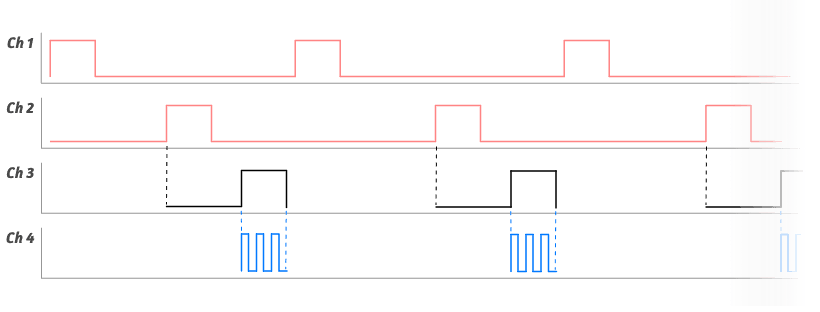
The Phase Pulse program requires a reference signal wait_pin. When the configured level of the reference signal is available, it will wait for x cpu cycles and then change to high for y cpu cycles. Before closing its cycle, it will wait for the inverted wait_level so it assured that the Phase Pulse Program runs only once, for each period of the ref signal. To perform multiple pulses, one could use a PWM signal with the wait_pin referencing the Phase Pulse signal. This is a first-class feature, so the Phase Pulse Program offers count_pin configuration option, which allows the user to set the amount of pulses it should be in high mode.
pid= "PHASE_PULSE"
Configugration parameters:
-
label(optional) -
pinthe output pin -
wait_pinThe pin which starts the program cycle. -
wait_level(optional, default=1) The level of thewait_pinwhich starts the cycle. -
count_pin(optional) If set, the user can change the amount of pulses of the referenced pin, instead of the usual duty cycle as absolute time.
UI Settings:
- Phs: Defines the phase or delay, before the
pingoes into high state. - D: This is time the pin is in its high state.
- OR Count: If
count_pinconfiguration is used, the program will start its duty cycle and count the on-off states of thecount_pinbefore it goes to low.
Examples
The examples are just for demonstration purposes, and depend on the actual settings through the UI.
Basic usage

{
  "title": "Phase Examp",
  "programs": [
    { "pid": "PWM", "label": "F1", "pin": "OUT1" },
    { "pid": "PHASE_PULSE", "label": "S1", "pin": "OUT2", "wait_pin": "OUT1" }
  ]
}
Long delay

Same config as before, it just depends on the setting of the Phs param in the UI.
Same count as ref

The program waits for the wait_pin, then delays, and then it stays in the high state as long it counts for 2 cycles (as an example) of the count_pin.
{
  "title": "Phase Examp",
  "programs": [
    { "pid": "PWM", "label": "F1", "pin": "OUT1" },
    { "pid": "PHASE_PULSE", "label": "S1", "pin": "OUT2", "wait_pin": "OUT1", "count_pin": "OUT1" }
  ]
}
4P System
At first glance the program seems to be complicated, but can be easily created using this basic set of primitives and it looks pretty simple and natural, once you understand the inner mechanics of The HackPWM Platform.

{
  "title": "4P",
  "programs": [
    { "pid": "PUSH_PULL", "label": "Push Pull", "pin": "OUT1" },
    { "pid": "PWM", "label": "Tesla", "pin": "OUT3", "wait_pin": "OUT4" },
    { "pid": "PHASE_PULSE", "pin": "OUT4", "wait_pin": "OUT1", "count_pin": "OUT3" }
  ]
}
Upload Configuration to HackPWM
You can create multiple PWM Systems and upload them to the device. All of the Systems will preserve their state and be available after rebooting.
Connecting to the device and upload files to the board can be accomplished in many ways, for this demonstration I am using uPIDE, which is open source, very simple and is perfect for beginners.
You can download it here https://github.com/harbaum/upide/releases (opens in a new tab) There are precompiled bundles for MacOS, Windows and Linux.
Example of uPIDE
- Connect your HackPWM with the Computer over USB
- Start the Program uPIDE
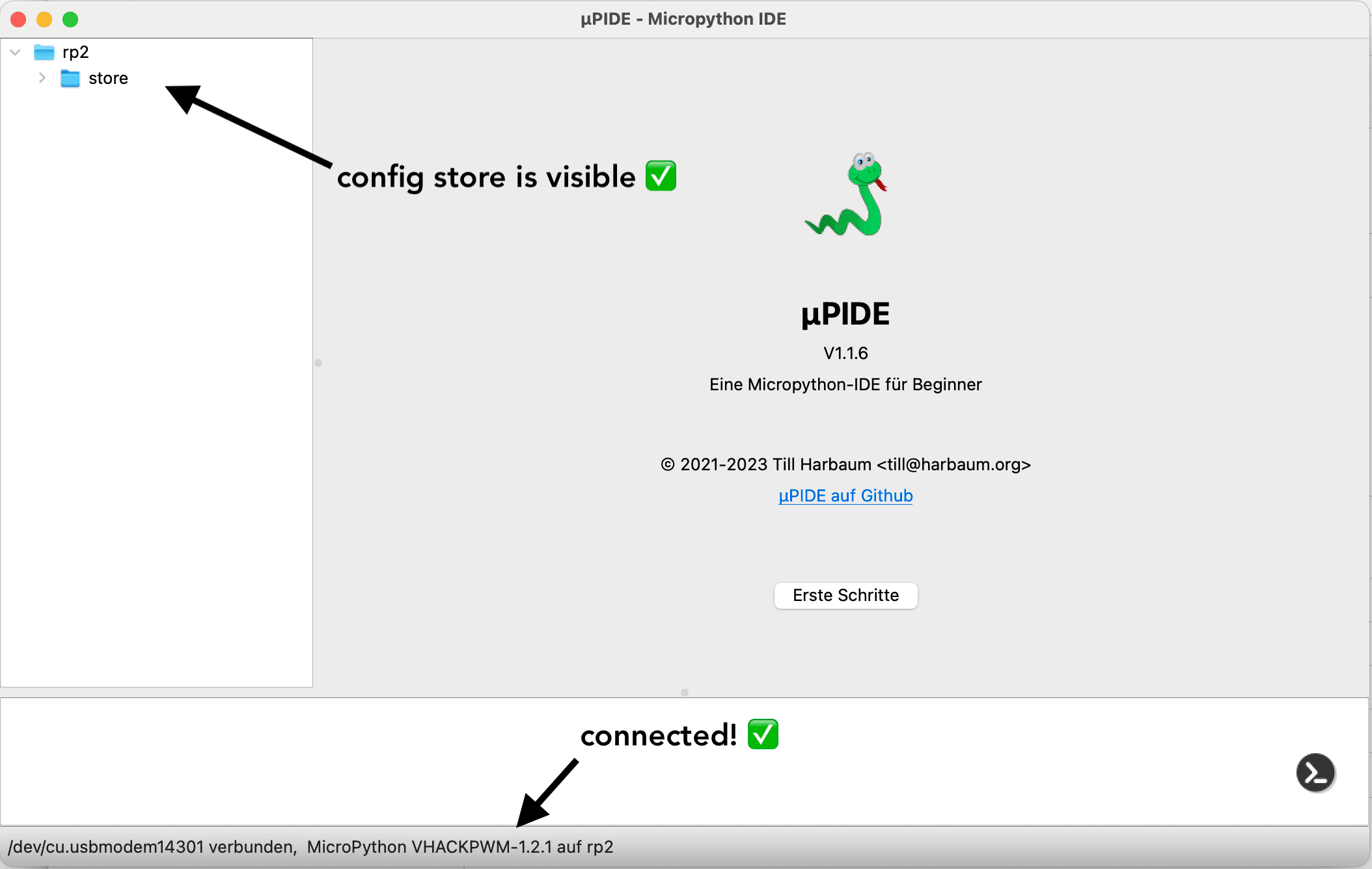
The program first searches for serial ports and after it has found the device it'll look similar to the next picture. In the bottom you will see the connected device, which should include the string HACKPWM, and on the left side you should see the configuration folder store.

- Open the folder store and look for the file:
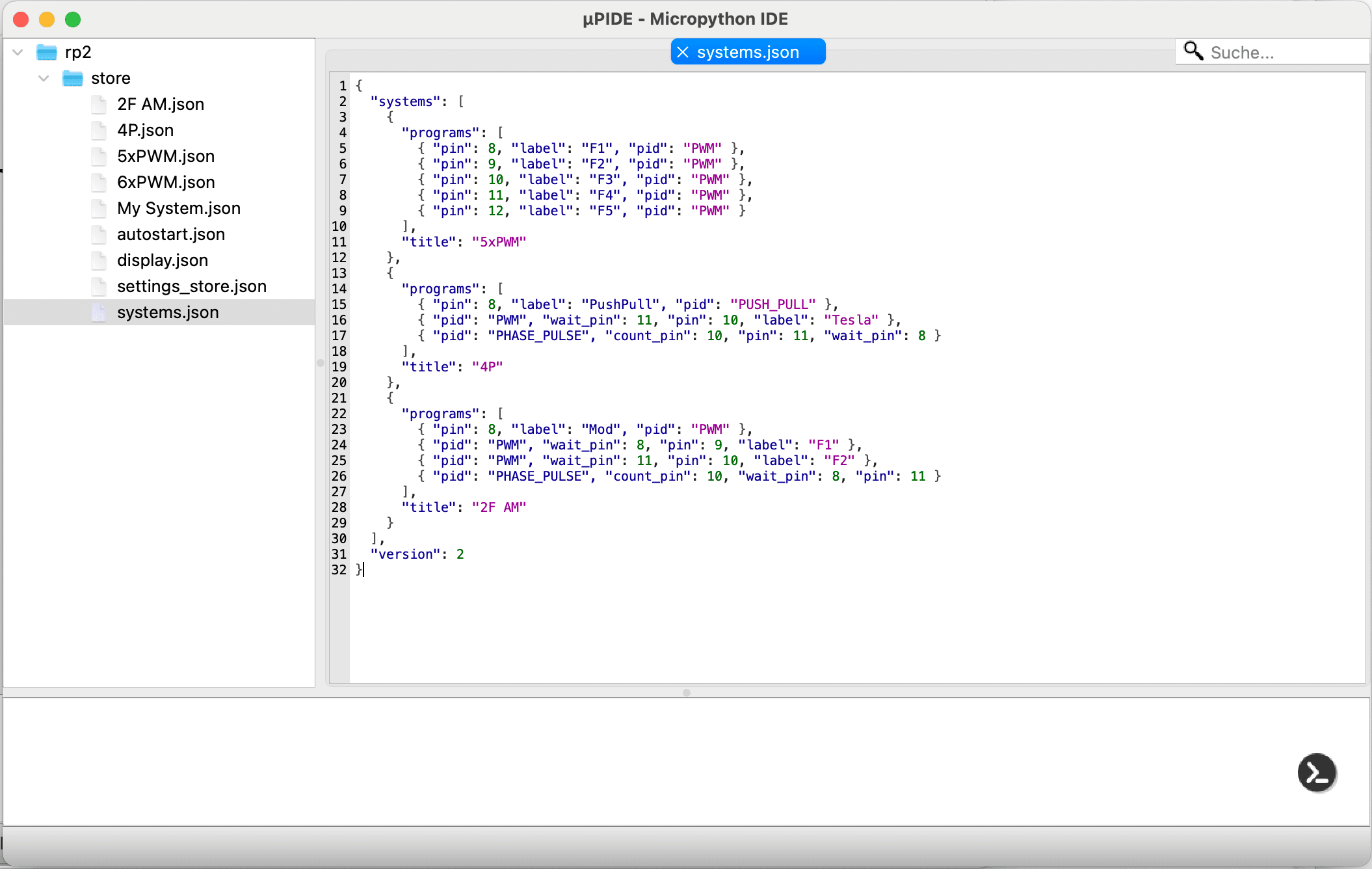
systems.json. This configuration file contains all currently available PWM Systems and their configurations.

systems.json file
The default /store/systems.json includes the program 6xPWM, 4P and 2F AM. It is using the integer numbers like 8 instead of OUT1 which are internally mapped to the actual pin number. By reodering the objects in the list, you can change the order in which they appear in the PWM Systems Menu.
Here is the default file. You can use the following code as reference or to reset your device, if you made a mistake. So no problem.
{
  "systems": [
    {
      "title": "6xPWM",
      "programs": [
        { "pin": 8, "label": "F1", "pid": "PWM" },
        { "pin": 9, "label": "F2", "pid": "PWM" },
        { "pin": 10, "label": "F3", "pid": "PWM" },
        { "pin": 11, "label": "F4", "pid": "PWM" },
        { "pin": 12, "label": "F5", "pid": "PWM" },
        { "pin": 13, "label": "F6", "pid": "PWM" }
      ]
    },
    {
      "title": "4P",
      "programs": [
        { "pin": 8, "label": "PushPull", "pid": "PUSH_PULL" },
        { "pid": "PWM", "wait_pin": 11, "pin": 10, "label": "Tesla" },
        { "pid": "PHASE_PULSE", "count_pin": 10, "pin": 11, "wait_pin": 8 }
      ]
    },
    {
      "title": "2F AM",
      "programs": [
        { "pin": 8, "label": "Mod", "pid": "PWM" },
        { "pid": "PWM", "wait_pin": 8, "pin": 9, "label": "F1" },
        { "pid": "PWM", "wait_pin": 11, "pin": 10, "label": "F2" },
        { "pid": "PHASE_PULSE", "count_pin": 10, "wait_pin": 8, "pin": 11 }
      ]
    }
  ],
  "version": 2
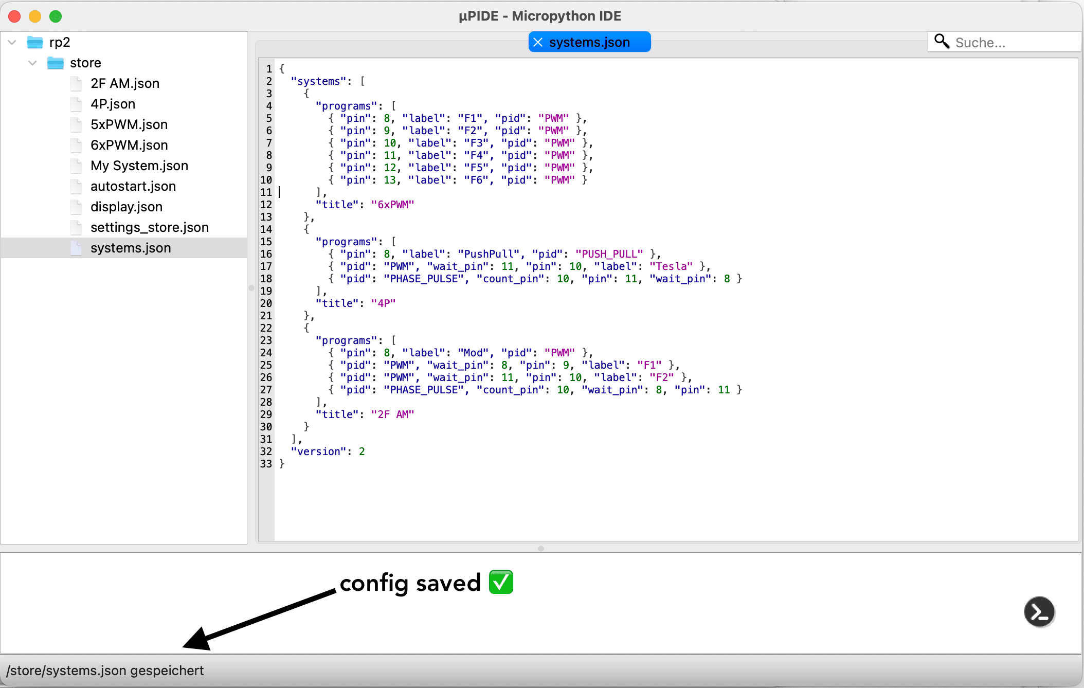
}- Make some changes to the file and click on the save icon.

- When changes are saved uPIDE will show a small message

-
Restart HackPWM by clicking on the RESET Button, you should now see the changes in you PWM System.
-
Done and enjoy!
For any questions, send an email to mail@plusminus.club or contact me via Telegram (opens in a new tab)